Low-power design · Updated October 2026
Low-power circuit design for battery devices
How to pick the DC/DC converter, switch off the parts that sleep, tell sleep current from safety leakage, and measure the result on a battery-powered board.
Quick answers
- How do you choose a DC/DC converter for a battery device? Start from the load: the output voltage and the minimum, typical and maximum current, then the input range the battery gives you. Converter choice
- How do you get sleep current down to microamps? Switch the rails off: an always-on clock or a load switch disconnects every part the device does not need while it sleeps. Power switches
- Is leakage current the same as sleep current? No. In a power-supply spec, leakage is current flowing to protective earth, a safety figure for mains equipment. Leakage
- How do you measure sleep current? With a power profiler that logs current over time down to the hundreds of nanoamps, which a handheld multimeter cannot follow. Profilers
What does low-power circuit design involve?
Power consumption is what limits a portable device. The battery sets its weight, its size and how long it runs, so the power circuit of the whole system gets as much design time as the processor or the radio.
The microcontroller and the radio decide how much charge each wake costs; we compare those parts in our low-power wireless MCU guide. The arithmetic that turns currents into days of runtime is in how to estimate battery life for IoT devices.
This article covers the board between the battery and those parts: the converter that makes the supply rails, the switches that turn rails off, the leakage figures in the datasheets, and the tools that show what the board really draws.
Four decisions, in order
- Size the load. Voltage and current for every rail, at minimum, typical and maximum.
- Pick the converter. Input range, regulation, isolation and package.
- Switch off what sleeps. Load switches or a regulator enable driven by an always-on clock.
- Measure it. A power profiler on the finished board, in every operating state.
How do you choose a DC/DC converter for a battery device?
Start from the output the system needs, then fit the converter to the input the battery gives. Four questions narrow the choice.
What does the load need?
The first number is the output: voltage and current. The voltage may carry a tolerance that depends on input voltage, load current and ambient temperature. Write the load current as minimum, typical and maximum, because a sleeping device spends most of its life at the minimum.
Unlike a mains supply, a DC/DC converter has no standard input voltage. Specify the input range the converter will see, from a full battery to an empty one.
Regulated or unregulated output?
Most DC/DC converters hold their output voltage tightly. A load that tolerates an unregulated output can use a smaller or cheaper converter. The choice usually exists only among small power converters.
Isolated or non-isolated?
An isolated converter has no DC path between input and output, which keeps electrical noise or a hazardous voltage on one side. One isolated converter can also give several output voltages.
A non-isolated converter shares ground between input and output. It is smaller and cheaper, and some types make a negative output from a positive input. Battery devices mostly use this kind.
Which package and mounting?
Converters that sit on the circuit board come as surface-mount (SMT) or through-hole parts, in single in-line (SIP) or dual in-line (DIP) pinouts. Chassis-mount and DIN-rail converters exist for equipment and industrial cabinets, open or sealed.
How do power switches cut sleep current?
A power switch connects a load to its source or to ground. Split the board into rails, switch off the ones that are idle, and the sleeping device draws only what the always-on part needs.
Separate rails
Several voltage rails let you power down one subsystem while another runs. They also protect subsystems from each other and control inrush current when a rail comes up.
Load switch
The basic building block. Used for power sharing, power sequencing, inrush control and cutting leakage from a load that is off.
Power multiplexer
Like a load switch with several inputs. It picks one of two or more power paths, for example USB or battery, and protects the inputs.
eFuse and hot-swap controller
Add current sensing, current limiting, under- and overvoltage protection and thermal shutdown to the input path. They suit boards that are plugged in live or see transients.
Ideal diode-OR controller
Drives an external MOSFET to block reverse current and protect against a battery fitted backwards, and wastes far less power than a plain diode in the same place.
Smart high-side switch
Protects loads that leave the board. It measures output current, reports shorts and open circuits, and has an adjustable current limit for capacitive, inductive and LED loads.
Is leakage current the same as sleep current?
No. Datasheets use "leakage" for two different things, and only one of them drains a battery.
Leakage to protective earth
In a power-supply spec, leakage current flows through the protective ground conductor. Without a ground connection it is the current that could flow from a conductive part to earth through any available path, such as a person.
AC leakage comes mostly from capacitance between the mains and grounded parts: EMI filter capacitors, gaps on the circuit board, insulation under heatsinks, and the winding capacitance of an isolating transformer. DC leakage applies to the end product rather than the supply.
Standby drain in a battery device
On a battery board the figure that matters is the current every part draws while the device sleeps: a pull-up, pull-down or voltage divider with too little resistance, a converter left enabled, a sensor left powered, or an internal RC oscillator running the clock instead of an external crystal.
The power switches above remove most of it. What remains is the always-on domain, which is why a good design keeps that domain to a clock and a wake input.
EMI, EMC and safety
Most electronic products sold must meet electromagnetic interference and compatibility (EMI and EMC) rules and safety rules. The rules keep a product from disturbing others and keep outside noise from disturbing it.
DC/DC converters can carry their own certification, but usually the complete product is certified and the converters inside it need none.
How do you measure sleep current?
With a power profiler. It plots the current, and the charge it adds up to, in real time over a period you choose.
A sleeping device draws microamps, then many times more for the short moment it wakes to measure or transmit. A multimeter shows one slow number and misses those bursts, so the average it suggests is wrong.
A profiler samples fast enough to catch each wake, switches range on its own as the current moves through several decades, and integrates the result into charge per hour. That figure goes straight into the battery-life estimate.
Measure every state the firmware uses: deep sleep, waiting for a sensor, radio receive and transmit. Then compare against the design budget before the board goes to production.
Nordic Power Profiler Kit
- Average and instantaneous current on Nordic development kits and on custom boards
- Supplies 0.8 to 5.0 V, set in software
- Measures up to 1 A, with accuracy down to about 200 nA and 0.2 µA resolution
- 100,000 samples per second, five ranges switched automatically
- Eight digital inputs for a basic logic analyzer view
- USB connection and the Power Profiler app in nRF Connect for Desktop
STM32CubeMonitor-Power
- Works with STM32 Nucleo development boards
- Measures from 100 nA to 50 mA
- The power board has a built-in display, so you can read current without a multimeter
Where this applies at Maxlab
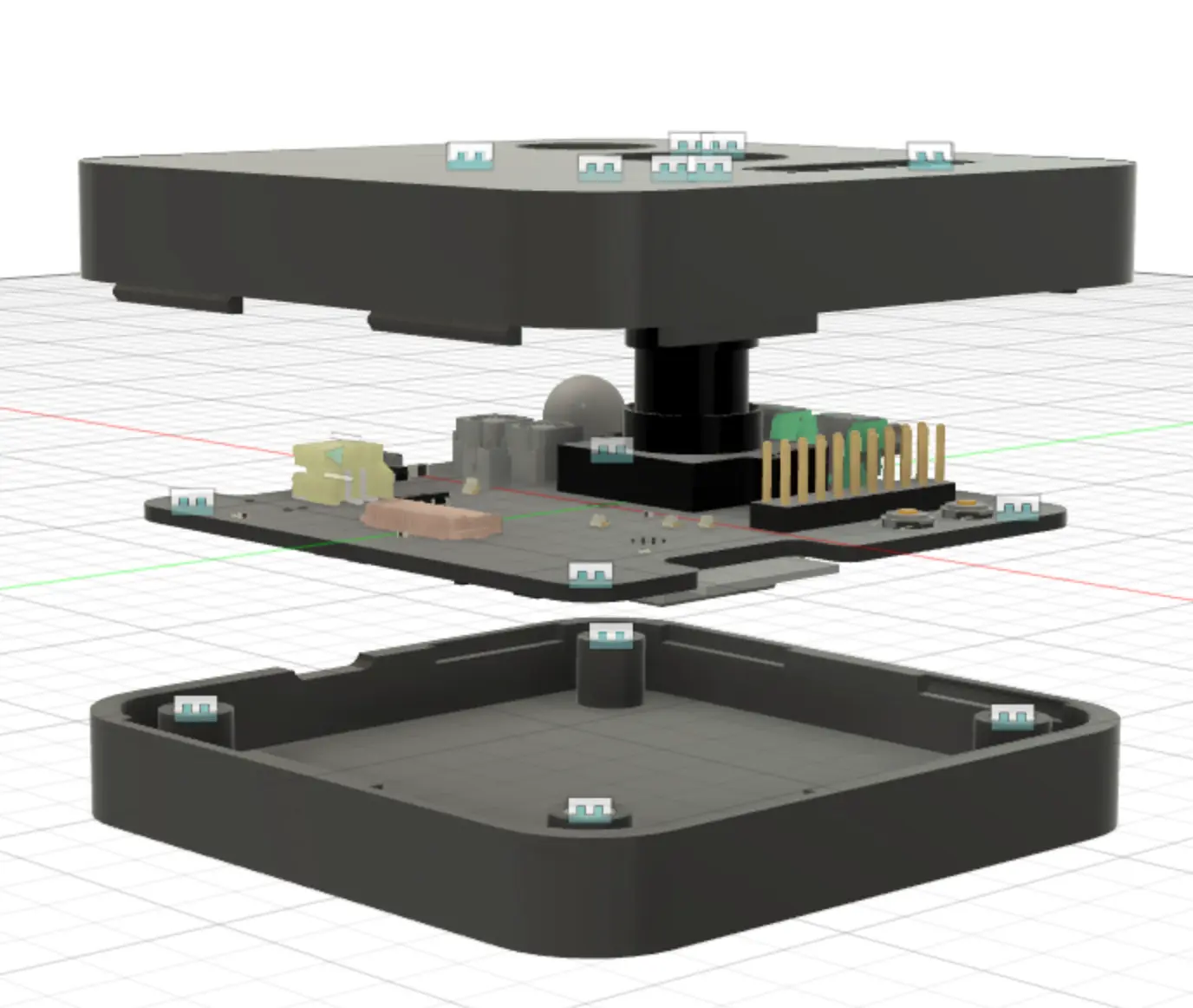
Tokay Lite, our ESP32-S3 camera board, is built around the power tree in the diagram. A programmable external real-time clock controls the whole power distribution, so the board draws microamps while it sleeps and wakes on a timer or on motion. It has a lithium battery charger and a JST-PH connector for a one-cell LiPo, and the schematic is open on GitHub under CERN-OHL-P-2.0.
The same platform runs the solar roof camera we built for a client: 9,500 units shipped, about six months on one charge. If your device has to run for months on a cell, our hardware and firmware services cover the power budget, the board and the bench measurements.
- Sleep control
- External RTC switches the power distribution
- Battery
- 1-cell LiPo, charger on the board
- Roof cameras shipped
- 9,500, about six months per charge
- Hardware licence
- CERN-OHL-P-2.0, schematic on GitHub
Get the power circuit right before the first build
Send us the battery, the parts on the board and how often the device wakes, and we will tell you where the current goes. We reply within 24 hours.
Or email [email protected] or book a 30-minute call.
Common questions
What is low-power circuit design?
It is the part of hardware design that decides how much current a board draws in each state. It covers the converters that make the supply rails, the switches that turn idle rails off, the parts that stay powered while the device sleeps, and the measurements that confirm the budget. On a battery device it sets the runtime as much as the choice of microcontroller does.
Should I use an LDO or a DC/DC converter in a battery device?
It depends on the gap between battery and rail voltage and on how long the device sleeps. A switching DC/DC converter wastes less energy when it drops a large voltage at high current. A linear regulator (LDO) is simpler and quieter. On a device that sleeps most of the time, compare the quiescent current of each part at your sleep load, because that figure runs all day. Some designs use both, or switch the regulator off entirely between wakes.
What is quiescent current, and why does it matter?
Quiescent current is what a regulator or converter draws for itself with little or no load. While the device is awake it hardly matters. While it sleeps it can be the largest current on the board, so check the datasheet figure at the light load your device sees in sleep.
How do I reduce a device's sleep current?
Split the board into rails and switch off every rail that is idle, using load switches or the regulator's enable pin. Keep only a clock and a wake input powered, use resistor values that do not waste current through pull-ups and dividers, and measure the result with a power profiler. On Tokay Lite an external real-time clock switches the power distribution, so the board draws microamps between events.
Why do you need fast logging to measure an IoT device's current?
Because the current changes faster than a multimeter updates. A device that sleeps at microamps and wakes for a few milliseconds spends its charge in bursts a slow meter averages away or misses. A power profiler samples many thousands of times a second and switches range automatically, so it records both the sleep floor and every wake, and adds them up into charge per hour.
Do DC/DC converters inside a product need their own EMC certification?
Usually not. Most electronic products must meet EMI, EMC and safety rules, but in most cases the complete product is certified and the converters inside it need no certificate of their own. Converters with their own certification exist and can help where a project needs them.
Can I power an ESP32 board from 5 V or a LiPo cell?
The ESP32 chip runs at 3.3 V, so 5 V from USB or the voltage of a LiPo cell has to pass through a regulator on the board first. Development boards include one. Tokay Lite takes power from USB-C or a one-cell LiPo on a JST-PH connector and charges the cell on the board.
Can Maxlab design the power circuit for my device?
Yes. We size the power budget, choose the converters and switches, lay out the board and measure every operating state on the bench before production. Send the battery, the parts and the wake schedule through the contact form and we reply within 24 hours. More on our hardware and firmware services.